Omega Onion IoT device
From here to ∞
Click image for enlargement.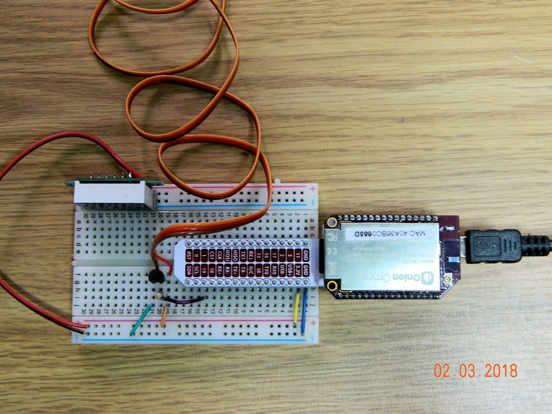
Out side one calls for warmth when the ambient temp is below 10oC and the inside one calls for cool is the room temps is above 10oC. Wired in series the effect is the turn on the fan when the temp is below 10oC out side and above 10oC inside.
Well this is starting on a computerized system to replace the manual one.
(02:03:2018)
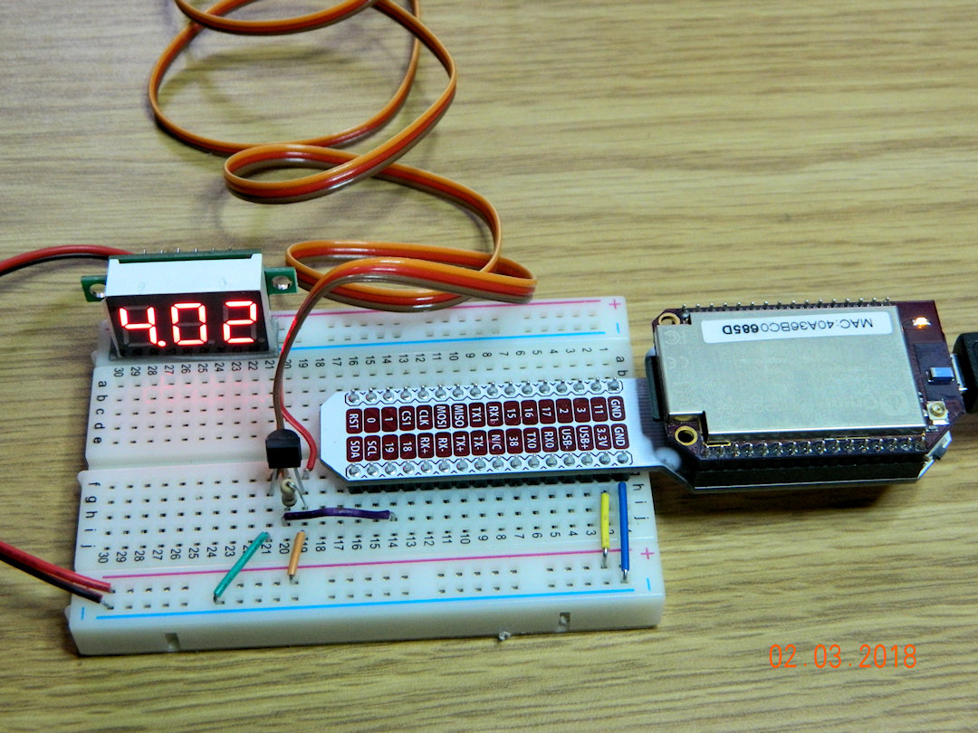
The silver thing on the right is an Omega Onion2+ - Unix based IoT computer costing about $12.00 cdn. The 4.02 thing shows the voltage on the 'bread board' (the white thing with all the holes). The orange/brown/red wire goes to a 1wire temp sensor hanging outside my window. And the black thing to the left end of the computer is the in door temp sensor.
(IoT stands for Internet Of Things)
(02:03:2018)
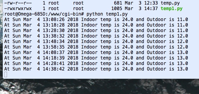
Ok so it's not much, but this screen grab was generated by Python code running on the Onion reading the two temp sensors.
(04:03:2018)
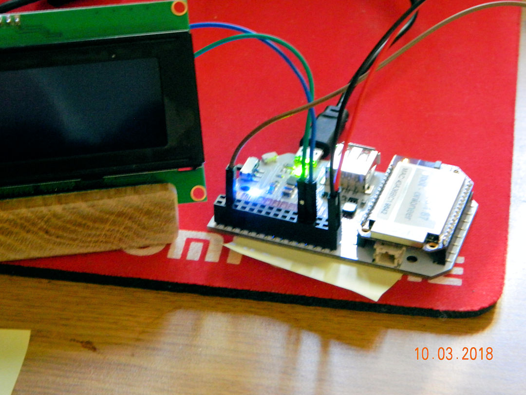
I would like to say I've added a 4x20 LCD display but maybe not. Display is there but I can't talk to it. It doesn't listen to me!
(10:03:2018)

I can now control the power relays based on the combination of cold room temp being above 10oC and the outside temp being below 10oC.. The red/green LED's (in the center) take the place of the fans for now. The red digital display is the current voltage on the +5v bus on the computer.
(16:03:2018)
This is my wiring attached to the top of the computer. The right side is connected to the existing sensors via a breadboard.
(27:03:2018)
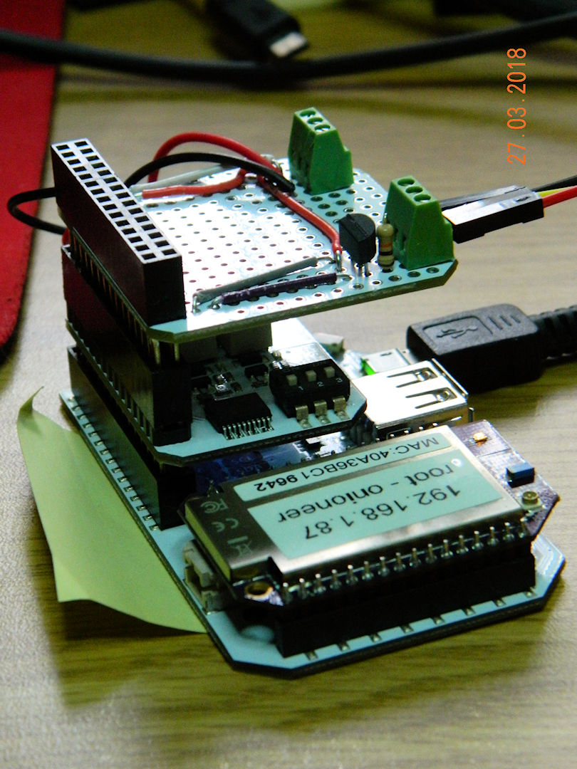

The OLED display has been added, after about 30 minutes of coding, and 4 - 5 hours of hardware debugging. I had to change the GPIO pin (signal out put) I was using, and the hardware documentation was WRONG.
(02:04:2018)
Better view of the stack of three card attached to the computer.
(02:04:2018)


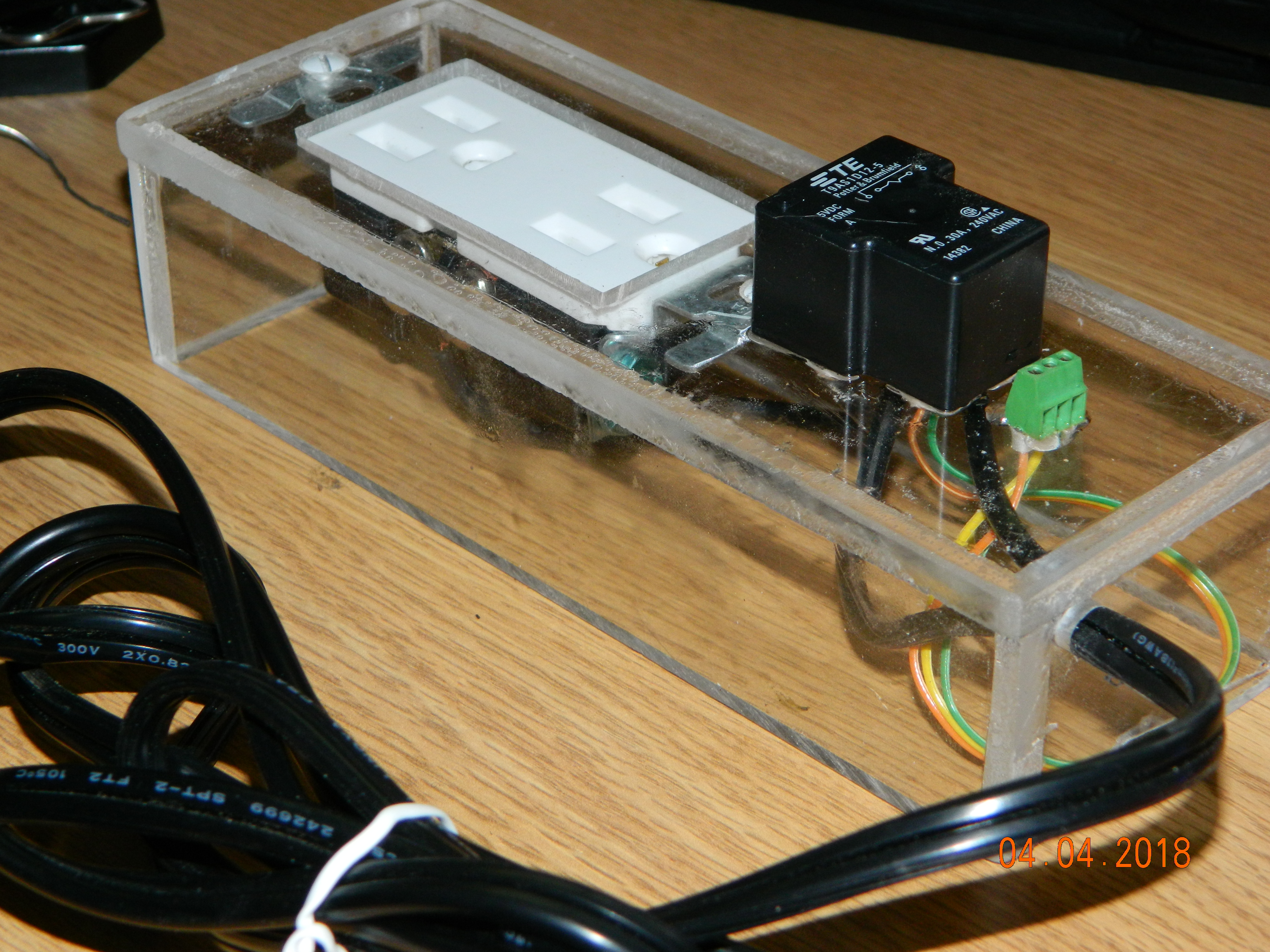
Next few steps are shop work, building boxes to keep all this stuff safe and separate from each other. This one is the box for the 110 volt power side.
(02:04:2018)
Power box set up. Black thing is 1 relay, 120v on one side and 5 volt from the computer on the other. Green is a header to plug in the 5 volt from the computer.
(04:04:2018)
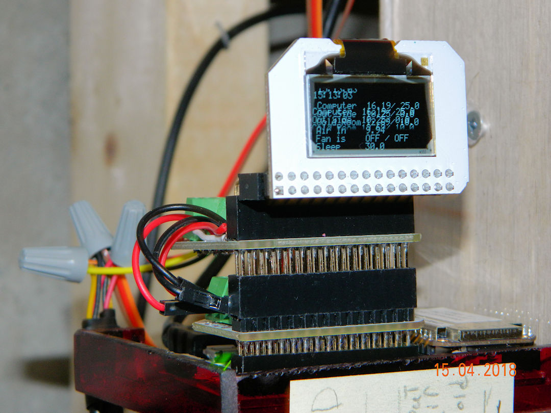
In place, and controlling the system. It is mounted on a special plastic shelf at eye level so we can read the display. Well at least some one with better eyes than me can read it.
(15:04:2018)
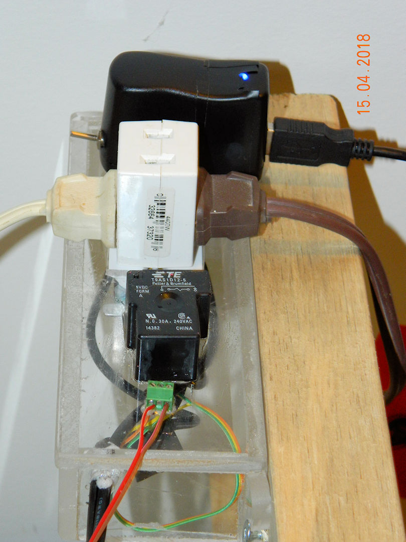
This is the power distribution panel. The top plug in is wired to always be hot (when the switch is on) to power the computer, and the bottom (with the cube tap) powers the fans when the system calls for cool. The black thing (with white writing) is the 110 volt relay that turns power off and on. This is a close as the line voltage gets to the computer. The green thing on the bottom of the stack is the 5 volt connection to the on board rely's on the computer.
(15:04:2018)
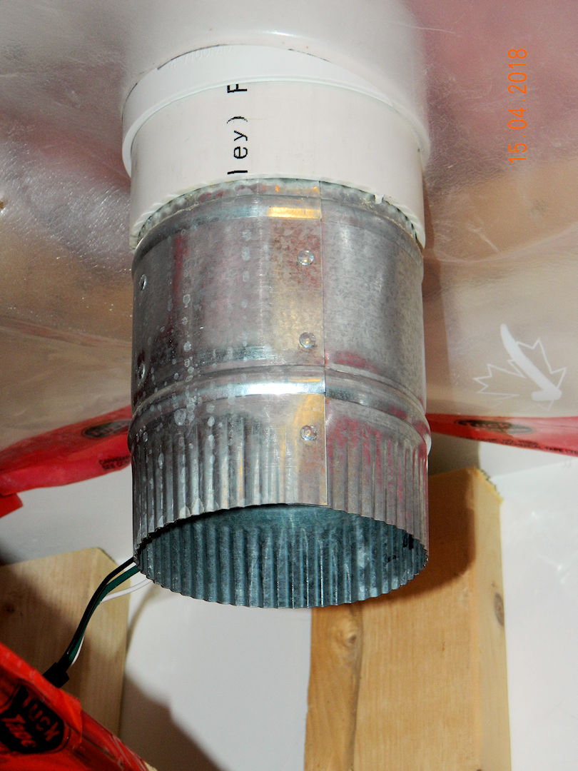
This is the out going air fan. Taking hot air out of the cold(ish) room. There is an incoming fan that brings cold air in as needed.
(15:04:2018)
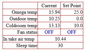
This is the status report from our internal web site. This was taken at 2:30 April 15th as I was adding the last pictures to the web site. The Fan status line with two OFF's shown. The first is the cooling fans status, and the second is for an auxiliary fan to cool the commuter (when ever the suppler gets the fans in that is)
(15:04:2018)
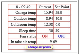
Software update (out with the old bugs - in with the new) added the ability to change the set points on the fly
(18:04:2018)
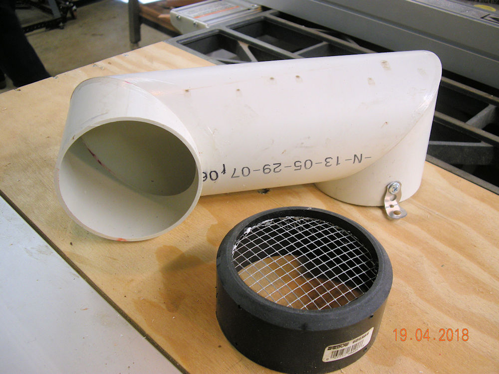
This is a modification for the intake air vent. Right hand end screws on the current vent to lower and direct the intake away from the out flow vent. I didn't know one could miter 5 inch ABS pipe and glue it directly to its self without pipe fittings. Now this is intake air we are using here so there will be no pressure involved. I'm not sure what would happen if there was pressure involved.
(19:04:2018)
| Click the Home button below to return to the main button menu. |

|